NEMO
Mechanical Lead of a team (4 people) working to create a humanoid robot capable of robust locomotion on ground
Note: All CAD shown is my personal contribution (concept and design). Assembly and testing performed by the whole team.
NEMO Overview:
-
Ultimate Goal: create a full scale humanoid capable of legged locomotion and intended for industrial use.
-
Problem: overall cost and scarcity of consumer accessible actuators with required performance (team is not currently developing custom actuators).
-
Solution: focus on the most complicated and important task (legged locomotion). Create a series of smaller scale humanoids to gain required insight, overall experience, and develop an efficient workflow between the mechanical, electrical, and software teams.
NEMO V1 Project Goals: (January 2025 - Present)
-
Create a humanoid robot able to walk untethered on flat ground (maximum terrain roughness TBD)
-
Provide a test platform for software team to learn how to minimize the sim-to-real gap while the mechanical team iterates the overall design to create full scale humanoid
-
Mechanical Team Goal: mechanical structure able to withstand large and unexpected loading that could be experienced during testing (overdesign for worst case scenario since replacing broken manufactured parts takes significant time)


Mechanical Overview:
-
Legs: 12 DOF total (6 per leg)
-
Hip roll, hip pitch, hip yaw
-
Knee (pitch)
-
Ankle roll, ankle pitch
-
-
Upper Body: 8 DOF total
-
6 DOF arms
-
Shoulder pitch
-
Shoulder roll
-
Elbow pitch
-
-
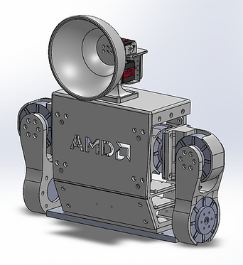
2 DOF head (actuated by 25 kg digital servos)
-
Serves as counter weight to raise the overall COM and allows team to test varying weight distributions
-
Head is largely cosmetic, aimed to make NEMO more approachable and allowed team to experiment with character features / expression
-
Overall Specifications:
-
Height: ≈3.3 ft / 1 m
-
Weight: ≈ 60 lbs / 27 kg
Actuation:
- Direct driven
-
Unitree GO-8010-6 Motors
-
Legs: 18 Motors (two motors per pitch joint)
-
Upper Body: 6 Motors
-
-
Powered by AMD NUC
-
Communication: Can bus
Control Framework:
-
Policy network: JAX
-
Deep reinforcement learning: MuJoCo
-
Deployment: ROS2
Design Process
The team analyzed existing designs and took inspiration from humanoids observed to have the most stable and "natural" walking gait. We noticed that most humanoids used similar knee and ankle setups, with the main variations being the DOF layout in the upper leg and relative locations of the hip actuators. The original design for NEMO V1 was created using DOF layouts inspired by the Unitree G1 (Unitree Robotics) and Atlas (Boston Dynamics). Due to time limitations and simplicity, the team chose to use a directly driven ankle instead of linkages extending from the calf (such as what is used in the Berkeley Humanoid (UC Berkeley)). An iterative design process was followed to ensure NEMO the best chance of being able to walk stably on the ground.

Outline

Inspiration (Unitree G1, Atlas, Berkeley Humanoid )

DOF Schematic

Design Iterations
NEMO V0.1 : General Concept

NEMO V0.2 : Block CAD

Humanoid Mass Properties, Simulation Prep

NEMO V0.3 : DFA, DFM, Range of Motion Checks


NEMO V0.4 : Redesign and Full Assembly PLA print
This version of NEMO was fully printed out of PLA to ensure correct tolerancing of the motor casings and fasteners. The team also tested the electrical system by deploying the walking policy with NEMO's pelvis fastened to the test stand. It is important to note that the desire to make NEMO as robust as possible led to overdesigning, with all structural components designed to be made out of 6061 aluminum and all motors being fully encased. During simulation it was discovered that this additional weight made it impossible for the robot to walk with only one motor per DOF. The team attempted to reduce weight by deciding to use a third party machining service which allowed for more more complicated part geometries (as can be seen in the difference of NEMO V0.4 from the block like NEMO V0.3), but this was not enough. This problem was ultimately solved by placing two motors in each pitch joint. This is a worthwhile tradeoff since NEMO V1 is intended as a proof of concept robot, able to endure the unexpected loading and crashing that might occur when deploying the new walking policies in an untested setup. Reducing weight (including the weight added by introducing the 6 additional pitch motors) will be a main priority in designing NEMO V2.


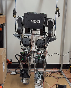
NEMO V1 Final Design, Manufacturing, and Assembly
NEMO V1's legs contain structural components made from 6061 aluminum (manufactured by Xeometry) and motor casings made from PLA. The robot's overall design emphasizes stability, symmetry, and part redundancy. For example, the aluminum motor casings on each section are identical, as well as the calves and PLA printed motor casings. Additionally, both legs are identical and common fasteners are used. Friction fit slots are utilized in the aluminum motor casings and foot attachment to strengthen the joints and alleviate strain on surrounding bolts. Ease of assembly was considered but not prioritized, since NEMO is designed to withstand forceful loading and should not need to be taken apart frequently. As discussed above, NEMO V1's upper body largely serves to raise the robot's overall COM. However, it does also allow the team to have more control over mass distribution forward / backward and able to add attachments to the elbow pitch joints. Note that motor rotors of these joints have been left exposed to allow NEMO V1 to sit upright on the test stand. Since there are no aluminum parts to attach to on the upper body, there are detachable brackets mounted to the side of NEMO V1's pelvis used to suspend the entire robot. An IMU and camera are mounted to the torso, with the team ultimately planning to have the AMD NUC located there as well.

_HEIC.png)


Testing Setup and Calibration
Harness and Test Stand:
In order to test NEMO V1, I designed a test stand and harnessing system. The stand itself is created from 3 x 3 x 6 ft 8020 framing, with additional framing attached using angled PLA printed brackets to provide cross bracing. I also designed aluminum plates to attach wheels (swivel caster with brakes) to the underside of the test stand, mobilizing the entire system. The harness setup was created using three ratchet straps attached to aluminum box tubing using threaded steel eye nuts. NEMO V1 can be easily lowered to the ground by adjusting the straps while the overhead suspension and cantilevered bar provide enough freedom from NEMO to maneuver while on the ground. The harness is tethered to NEMO V1's aluminum pelvis, providing stability in case the robot loses balance.


Motor Testing:


NEMO V1 Calibration:
The Unitree GO8010-6 motors only contain one encoder on the motor rotor to determine the position. However, due to the reduction ratio from the motor's gearbox, the output shaft loses its "zeroed" position after a certain amount of rotation. I designed PLA printed calibration blocks to interface with the geometries of NEMO V1's ankle, calves, and pelvis, effectively locking them in a consistent starting position. A section of 8020 framing is slid between the pelvis and calf connections, using NEMO V1's offset COM to force the legs into an upright position. Future versions of NEMO will likely include external encoders to simplify this process.


NEMO V1 Testing: Closing Sim-to-Real Gap


Current Work:
The team is currently working on testing the walking policy by deploying it with NEMO V1 suspend on the mobile test stand. Current issues include the preemptive shutdown of motor drivers, which the team is investigating by testing sections individually and redesigning the electrical setup.
Future Work:
The team will work on the mechanical design of NEMO V2 to reduce overall weight and reduce the total actuator count to one per DOF. Custom PCBs will be designed to clean up the electrical system while insights from the software team will provide the basis for further design considerations.